|

...World Wide Distributor of Beryllium-Free Copper Alloys...
Manufacturer of Standard & Custom Components
![]()
Site Updated Often! To ensure proper viewing please Refresh page &
MAKE SURE YOUR BROWSER IS SET TO UPDATE AT EACH VISIT
![]()
Maintaining The Thermal Balance Core To Cavity: The Key To Cooling Efficiency Dr. Paul Engelmann and Eric Dawkins |
Abstract |
| Achieving parts with maximum dimensional stability coupled with minimum cycle times, is a goal of most molders. Previous studies have shown that a majority of heat contained in the molded part is removed through the core of a mold. Application of high strength, high thermal conductivity copper alloys to core, cavity, and gate areas, has led to some revelations. These data shed new light on the effect of change in temperature vs. change in thermal conductivity. |
Background and Introduction |
| A thorough understanding of
where greater heat removal can improve the dimensional stability of a part is an important
step in the quest for zero defect products. Research into the effects of applying high
strength, high thermal conductivity copper alloys to injection molds has been underway
since 1995 at Western Michigan University (WMU). Researchers gathered non-structured
anecdotal information about the experiences various professionals in the plastics industry
had with applying copper alloys to injection molds. Although the majority of
experiences related to the research team were positive, those people with most extensive
experience reported times where application of copper alloys were not always effective in
reducing part warpage or cycle time. Although this response represented a small fraction,
it nevertheless raised the question about whether high thermal conductivity was
necessarily better for all applications. Early studies focused on use of copper alloys for the core section of a mold (1). Application of both normally watered copper cores and non-watered copper cores attached to watered copper chill plates has been shown to significantly improve the dimensional stability and cycle time required to mold a given part (2). The other logical piece of this investigation was to determine the effect of applying copper alloys to the cavity side of the mold. As the majority of non-favorable anecdotal experiences related to cavity applications of high thermal conductivity alloys. It was decided that a thorough investigation should be undertaken to determine the range of effects that high thermal conductivity materials had dependent upon the processing strategy. Cooling analysis predicted that a majority of heat Load was given up through core-like structures in the mold. That is to say that a positive structure, or core, tended to have a higher heat load per unit of mass. This was most pronounced when the part shrunk onto the core, thus losing surface contact with the cavity. Instrumented studies on the test tool at WMU confirmed that a majority of the temperature swing, and thus the heat removal, was proceeding through the core of this tool (3). It was decided the relationship between core material and cavity material needed to be investigated. Since the submarine, or tunnel gate, was located in the cavity section of the tool, the relationship between cavity material, gate size, and cavity temperature also needed investigation. This was based upon the hypothesis that a higher thermal conductivity alloy could cause premature gate freeze and therefore compromise the processors' ability to pack out me part. Inability to pack the part could result in both dimensional changes and an increase in defects such as sink. |
Experimental Design |
| The study utilized an
incomplete block design in which the various cavity/core treatments were applied over a
sequence of equally spaced cycle times. The set of cycle times used, shifted as
appropriate for each treatment combination. This shift conserved resources while
still allowing the key responses to be measured for each treatment group. This strategy
enabled the research team to review various gate sizes between .81 mm (.032") and 97
mm (.038"). Gate inserts were produced out of both type 420 SS and C18000 as a
representative copper alloy. In addition, a series of mold cooling temperatures were
selected. Water temperatures ranged from 100 C (500 F) to 660 C (1500 F). The mold used for the experiment was a 33 mm bottle cap mold
with interchangeable cores and core mounting plates with a spiral baffle in the cores. The
resin used was a Huntsman polypropylene copolymer. All work was done on a VanDorn 77 metric ton (85-ton) hydraulic toggle injection molding. The injection screw was a 35 mm (1 3/8" diameter) with a 20.6 cc (5 ounce) shot. Mold water was regulated by a AEC mold temperature controller and a 2.7 metric ton (3-ton) Thermal Care chiller. Circuit water was monitored on all zones for flow rate, input and output temperatures, and pressure loss through the circuit. Cavity pressure, screw position, and hydraulic pressure were monitored by an RJG Technologies DART system. Thermocouples in the cores were embedded in heat transfer compound eliminating air gaps to read more accurate temperatures. The thermocouples were connected to an analog input computer card. Readings were processed with Strawberry Tree's Quicklog PC data acquisition & control software. The parts were allowed to stabilize in a testing lab under ASTM environment guidelines for a minimum of 96 hours. A gage was constructed to measure part warpage. Part warpage was determined by the amount of deflection across the surface of the bottle cap. A measurement was first taken along the edge height of the bottle cap with a digital plunger indicator. Another measurement was then taken at the center of the bottle cap. The center measurement was then subtracted from the edge measurement in order to determine warpage. Gage repeatability and reproducibility (R&R) was done using a standard ANOVA method. |
Findings |
| Examination of various core
and cavity combinations yielded the following information about the relationship of copper
alloys to their position in the mold. All of the baseline copper alloy core data
were drawn from experiments using a type 420 SS cavity. It was expected that substituting
copper for the stainless steel cavities would improve performance with the various copper
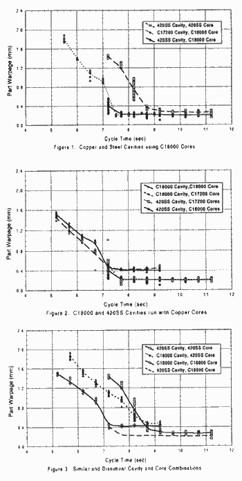
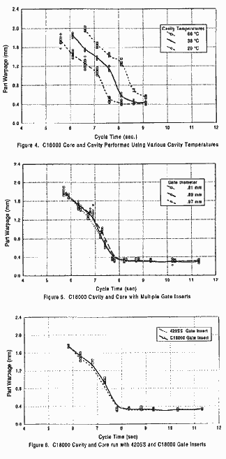
cores. Figure 1 compares the effect of substituting C17200 and type 420 SS cavities while maintaining a C18000 core. In addition, the data for type 420 SS cavity and core was included as a reference comparison to standard practice. It can be observed from this graph that the type 420 SS cavity using the C18000 core, had the most uniform performance and provided acceptable parts at a faster cycle than any of the other combinations. The line for the C17200 core using a C18000 cavity began at a shorter cycle time due to the faster gate seal with a copper cavity It is interesting to note that the final warpage in parts produced by the C17200 cavity with a C18000 core was the same as those from the type 420SS cavity with a C18000 core. Since the gate was located in the copper cavities, it froze approximately two seconds faster than the gate located in the steel cavity. A premise of this study was that even though it is sometimes done as industrial practice, parts should not be ejected prior to gate seal. Therefore, the shortest possible cycle for the C18000 core, type 420 SS cavity was completely dictated by the gate freeze time using the steel cavity. It was, therefore, logical to assume that although parts may have been of diminished quality, they could have been ejected in less than 7.3 seconds using the type 420 SS cavity in combination with the C18000 core. Figure 2 demonstrates that the amount of warpage in the final part, is dependent upon the cavity material. In this example, the C18000 cavity using either C17200 or C18000 cores produces more warpage than the type 420 SS cavity with either copper alloy core. As was previously noted, the parts molded using the C18000 cavity were able to be ejected earlier than those parts molded using steel cavity due to gate freeze times. The ideal cooling curve would be shallow and have the smallest minimum warpage in the final product. It may be noted in Figure 3 that the slope and general configuration of matched alloy core and cavity sets was very similar. The shape of the cooling curve produced, using a copper core and a copper cavity, was very much like the shape of the cooling curve using a steel core in conjunction with a steel cavity. It may be noted here that both the final warpage achieved and length of rime required before solidification allowed ejection of the part did differ. In this case, parts produced with a C18000 core and cavity were ejectable at 5.2 seconds. However, their warpage did nor stabilize until roughly 7.2 seconds. Parts produced using the type 420 SS core and cavity could not be ejected until 7.2 seconds and those parts did not stabilize until 9.2 seconds. In addition, when the differential was reversed by using a steel core and a C18000 cavity the poorest overall warpage curve was achieved. Comparison with the optimum type 420 cavity and C18000 core demonstrates the profound affect of higher thermal conductivity in the core. Therefore, the shape of the cooling curve appears to be dependent upon the differential, or lack thereof, between the cooling rates offered by the core and cavity. It was theorized that in order to favorably alter the heat removal between core and cavity of the same material, that the core and cavity should be run at different temperatures. Figure 4 graphically illustrates what happens as the cavity temperature was raise while holding the core water temperature uniform. Using a C18000 core and cavity, the water temperature of the cavity was raised in increments of 100C (500 F). This produced interesting results. Although the three curves are similar in shape, it is interesting to note that the curve using a 100 C to core water and 660 C (1500 F) cavity water shows a more pronounced step in the curve. This directly relates to the glass transition temperature of polypropylene. In other words, raising the cavity temperature not only made the cycle longer but also probably increased the crystallinity in the resulting parts. It was also suggested the part warpage phenomenon might in fact be influenced by gate size. Therefore, gate diameters of .81 mm (.032") through .97 mm (.038") were used. This range of testing represented a 41% increase in total area to be solidified. Yet, the resulting cooling curves in Figure 5 are virtually identical. It was expected the .97 mm (.038") gate should have stayed open longer prior to gate freeze than the .81 mm (.032") gate and that this should yielded a better packed part. Thus, achieving a lower overall warpage baseline. Notice that although there were some very minor differences in the curve itself, there was no discernible difference in the baseline whatsoever. The other proposed method of altering gate freeze was the use of a stainless steel gate insert. Since the gate insert represented the top of the runner, gate, and a section of the side wall, it was proposed that a stainless steel gate insert should produce a long gate freeze time. Again, allowing for additional packing of the part. Figure 6 illustrates the C18000 cavity with C18000 core using gate inserts of stainless steel and C18000 copper. Both gates were identically sized at .97 mm (.038") in diameter. Figure 6 shows that there was no appreciable difference either in the baseline or in the solidification curve with this modification. |
Conclusions and Recommendations |
| The data presented here
leads one to the following understanding. First, for this mold, the primary factor that
affected warpage was the heat removal from the cavity vs. the core of the mold. This is
not surprising as it has been supported by numerous other studies. However, there are a
series of important nuances. These data show that a thermal differential between the cavity and the core is important. In the past, it had been suggested that simply heating up the cavity side of the mold might accomplish the same thing. However, these data clearly indicate that running the cavity hotter than the core only lengthened the cycle time, and made the part warpage more pronounced. Probably the most complicated decision is how to achieve the thermal balance. The copper core, with a steel cavity, clearly produced parts with minimum warpage in the least cycle time. However, use of a copper cavity did achieve a faster gate seal. Therefore, if part warpage is not a significant consideration, using a copper cavity with a copper core could allow recovery of the injection unit sooner, than with any other combination. In addition, when lower thermal conductivity C17200 was used for a cavity. and higher thermal conductivity C18000 was used for the core, low final net warpage is achieved. In fact, the C17200/C18000 combination yields the same final warpage as the optimum C18000 core using a type 420 SS cavity. In a large volume part, this might allow an earlier recovery of the screw, which could in fact lead to an overall shorter cycle. It is also reasonable to assume that since C17510 and C18000 have very similar thermal conductivities, that a C17510 core and a C17200 cavity should behave similarly to the C18000 core with the C17200 cavity. It is important to note that applying a copper cavity with a steel core throws the thermal balance in the wrong direction. This situation should be avoided as it does not afford any benefit either to the part quality or cycle time. However. a core-like structure, on the cavity side of the mold, would behave as score, not as a cavity. In each situation, it is important to assess what type of structure is in the mold rather than which side of the mold the structure occurs on. Cooling analysis is therefore, an important piece of overall cooling design. The more complicated the core to cavity structures are, the more difficult it will be to maintain the thermal balance without using some method of verification. It is the recommendation of the research team that core-like structures be made of high thermal conductivity, high strength copper alloys, unless something about a given mold design defies their use. In other words, it is time to start asking why a core structure is not made out of a high strength high thermal conductivity copper alloy rather than asking if it is an option that should be considered. |
Acknowledgments |
| The research team at
Western Michigan University wishes to acknowledge the significant support of a number of
organizations and individuals. The Copper Development Association Inc. for providing the
financial support for this research. Performance Alloys & Services Inc., Brush
Wellman Inc., Copper and Brass Sales, and NGK Metals provided alloys for the mold. Research assistance was also provided by Bob Dealey,
Cliff Moberg, Dr. Dale Peters, Jay Shoemaker and Scott Smyers. |
References |
|
| KEY WORDS: mold, core, cavity, copper |
  |
|
|
|
|
Copyright © 2024 by Performance Alloys &
Services, Inc |
